Wireless Temperature Sensor Complete
2016-06-29 23:50 - Making
I've "finished" my wireless temperature sensor project. At least the first version.
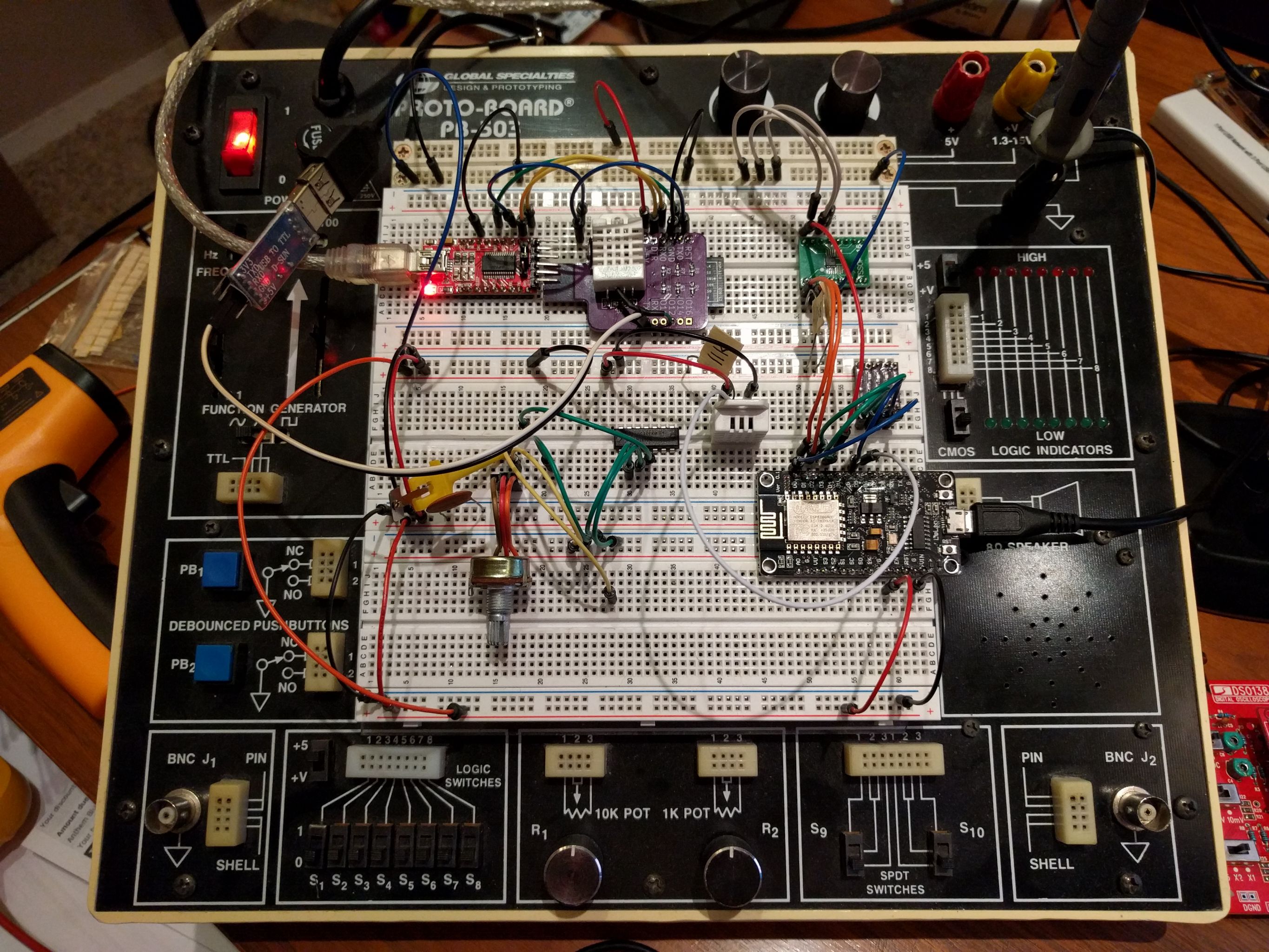
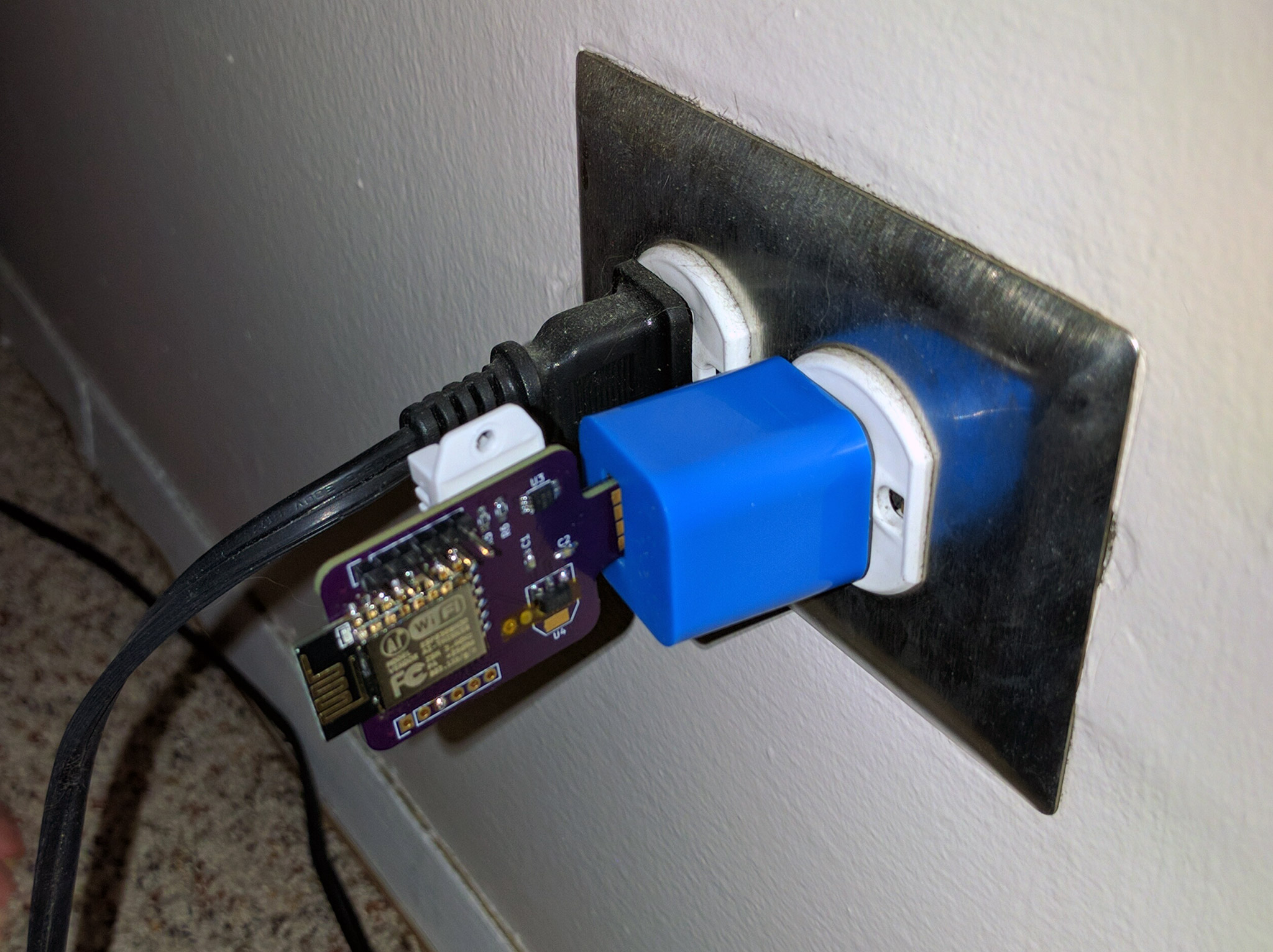
The first picture here is the final test before "done", on a breadboard. It's assembled and plugged in there. Look at the middle picture and you can just see (U4) the first mistake. The power regulator isn't the size I thought it was. I got lucky that I could force the smaller chip to line up just good enough to use anyway. Then on the breadboard I realized the second design mistake. I knew of the idea of designing thermal relief into a board like this, with temperature sensor included. I neglected to do so, however. Turns out the chip running the WiFi pushes the temperature on the board up around ten degrees above ambient, and with the (surface mount) temperature sensor (U3, top right of the mostly-in-focus middle picture) also right on that board, under an inch away, it doesn't give the sort of readings I want.
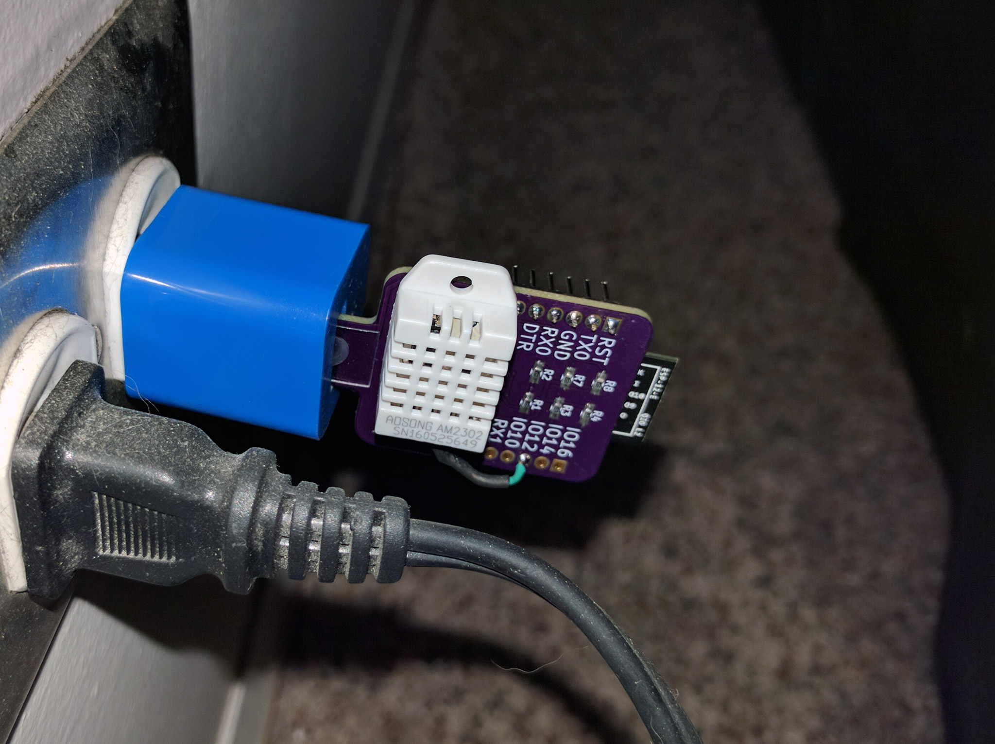
Luckily the next day the pair of AM2302 sensors I ordered arrived in the mail. These are the same as the DHT22, which is compatible with the DHT11. I've had some DHT11 units for a while — they're awful quality (for this application), but they do have a passable humidity sensor. And I had nothing else to do with them, so I left a place to put one in. The DHT22/AM2302 sensors are much better for this project. And they're not surface mount, so they won't be corrupted (as much?) by the heat of the processor/WiFi work. It's the white plastic box visible in all three pictures (most obviously in the last one).
The new sensor was pretty easy to hook up to the dev board (bottom right of the first picture), which is a cheap NodeMcu knockoff. But I couldn't get it to work in my board. Turns out I selected an arbitrary pin (11, GPIO9) based on proximity/convenience on the board. That pin won't work for this application (argh!), and I didn't test that before getting the board made. So, as you can just see in the last picture, the data pin is lifted, extended, and run over to one of the extra GPIO breakout points I included "just in case" (phew!) which works.
So far it's been plugged in since last night and it's happily answering my queries for data. I'm running a quick test to see what sort of data it produces overnight. But overall, it looks to be in a good enough state to begin using.
This is my first ESP8266 project, to mixed results. It's really convenient to have a programmable WiFi capable microcontroller, but programming is a bit of a pain, all the networking smarts bulk up the programs a lot, so they take a while to upload. Plus it's a bit of a dance to get it in the right mode to accept the programming. For my board, I ended up relying on the second UART port for diagnostic output, I couldn't get reliable data out of the primary one. If I have another small project where WiFi interaction would be useful, I'll probably give it another try but I'll be cautious.
That second project might be a second version of this very project. I'd like more sensors so I could know, for example, how much (if any) difference there is in temperature in various parts of my apartment, especially "upstairs" in the sleeping loft. That's why I made it wireless: so it's easy to put wherever I want, as long as I have power available to run it. I can fix the mistakes I know of, and perhaps try again with a new better version.