Teardown: Leader LPS-152 Power Supply
2015-07-31 21:13 - Making
If you browse the recent archive of my making topic posts, you'll see I've been having lots of fun on various electronics projects for several months. A short while ago I managed to pop the (expensive HRC) fuse in my meter and let the magic smoke out of (thankfully only) a resistor when I probed the wrong current path in the circuit I was testing. Why? Because I was using the wrong power supply, and when I did so, the full eighty watts or so that the (laptop brick) supply in use managed to pump through the two watt resistor in question, not to mention sending almost 4 amps through the 0.44 amp limit current range I was using in my meter, before I saw and reacted.
A "proper" electronics bench power supply supports not only setting which voltage but also which current (limit) to provide. If I had been using one, knowing that I only expected a couple dozen mA to be consumed, I would have set an appropriate limit and never applied enough power to damage anything. I've been getting away with simple fixed-voltage supplies like USB ports, 5V USB adapters, and these laptop power bricks for too long. So I started scanning eBay for a power supply that would let me limit both the voltage and current to an arbitrary level. It took a while, since these things are very expensive (relative to my expectations for such a "simple" device), for me to pick one I was willing to pay for. I ended up with this, a vintage Leader LPS-152 power supply.
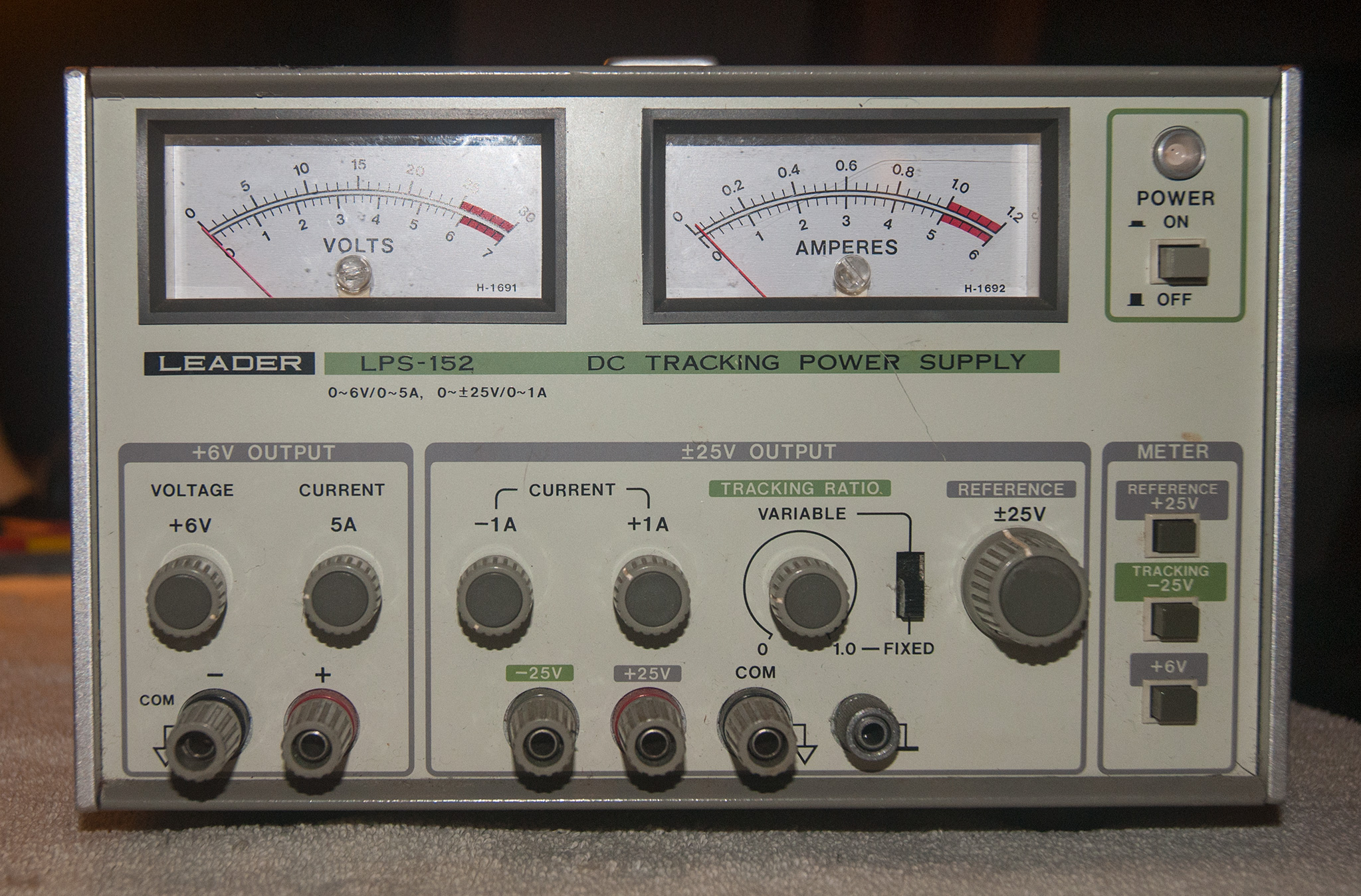
Here's the front panel. A couple minor scratches and scuffs, but quite good overall. Analog meters, but they're fine for the purpose. This is a triple output supply: it has one output that goes from 0V to 6V, and up to 5A, plus one each that goes from 0 to +/- 25V, and up to 1A. I'll rarely if ever use the negative supply rail, but it's possible to combine them to produce up to 50V safely. The first thing I did was test all three, and they work great, both to set the voltage and to limit the current.
I managed to find a copy of the instruction manual online (the internet is great!), which has not only a complete set of operating instructions, but detailed testing and calibration procedures as well. Plus a full parts list, PCB layout diagram, and schematic! There's a ton of passives and discrete diodes and transistors. And only four ICs, all opamps. The design dates this item a bit. So let's open her up and take a peek inside!

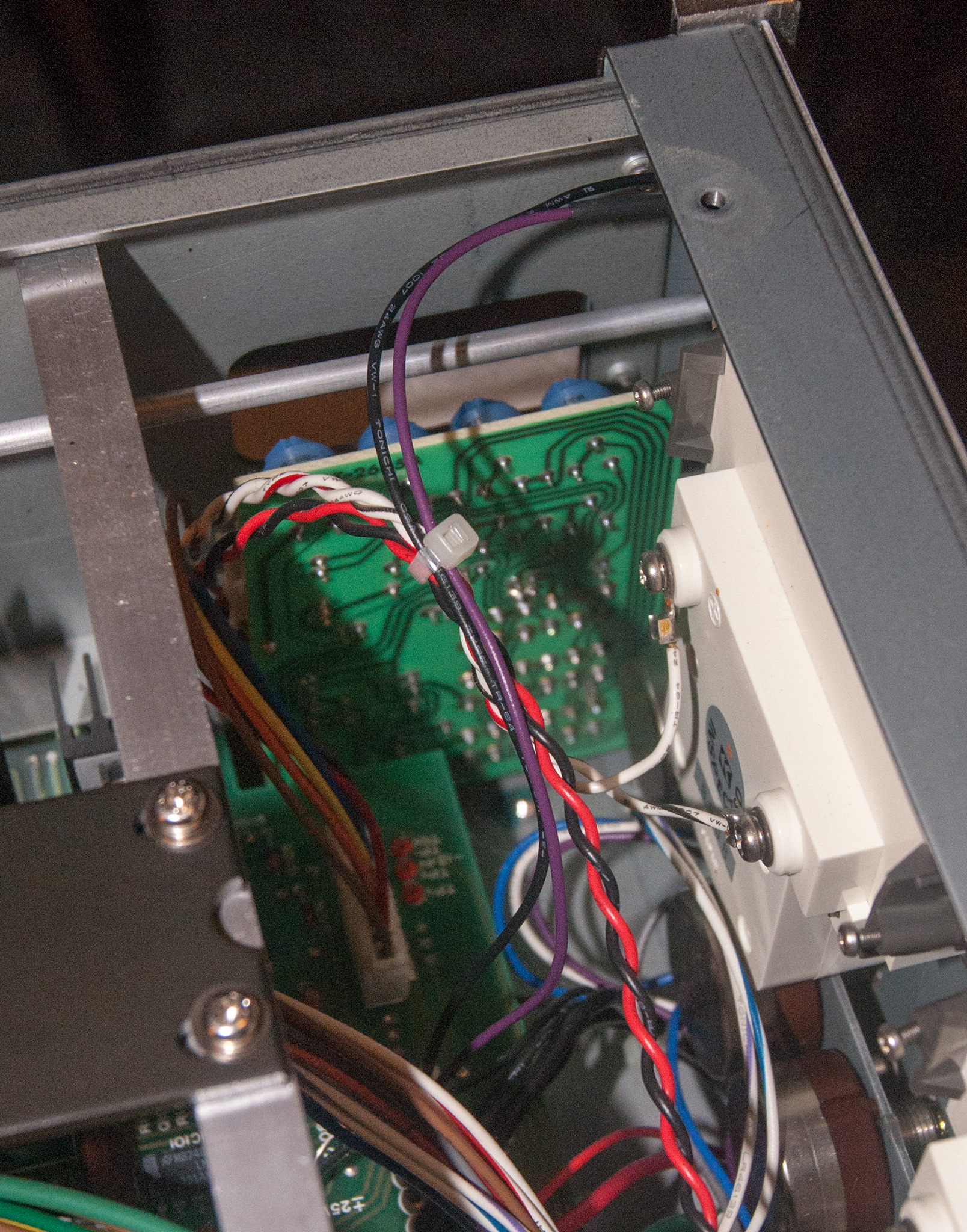
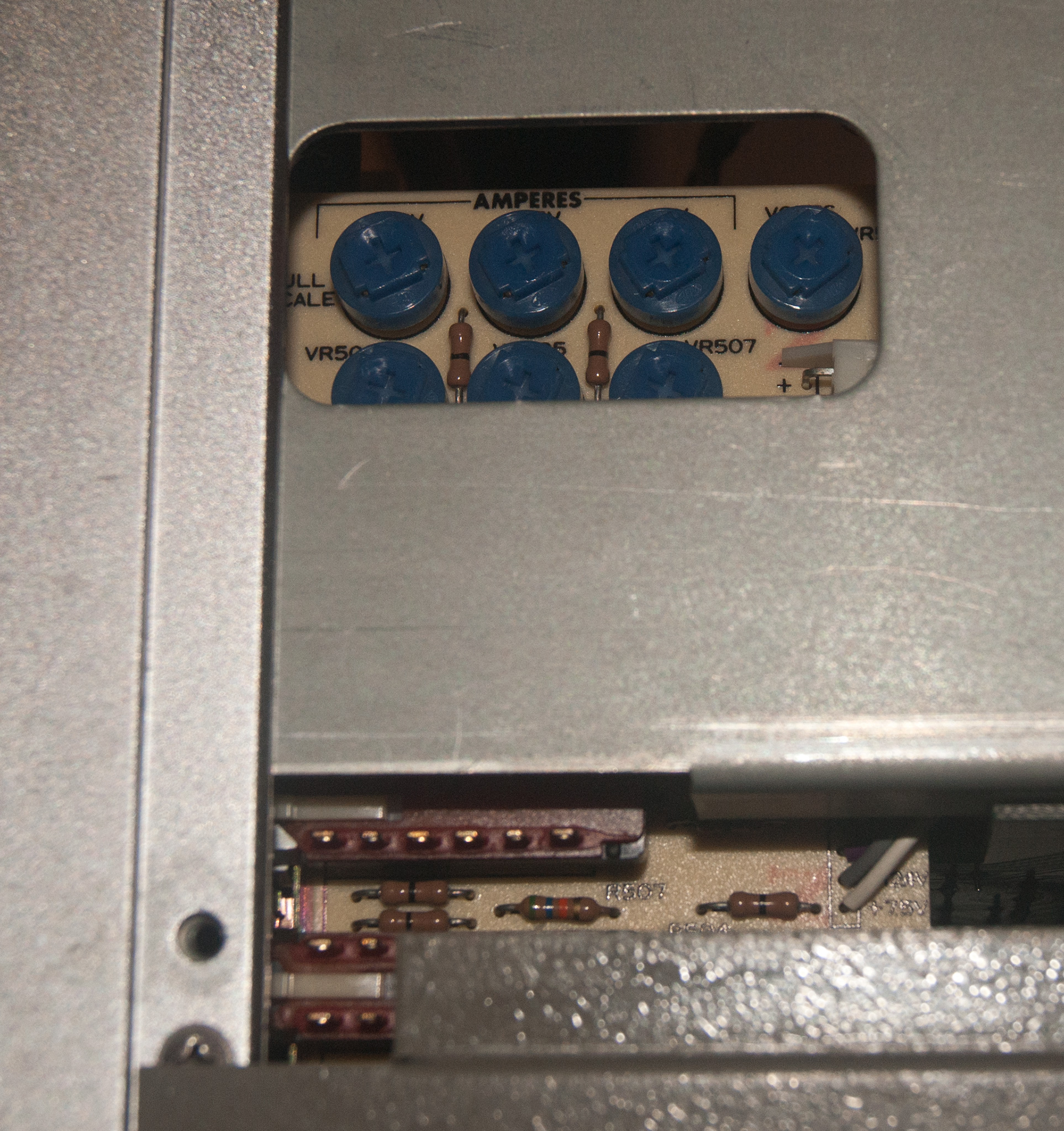
First we've got an overall view, from above. The front of the supply is at the left, with the giant heat sink at the rear is on the right side of the image. The giant transformer dominates the image at the top middle, with a black metal bracket bolting it to a support crossing the width of the supply. I like the attention to detail in here. Most everything is attached to the PCB that fills the background of the image. Next we see the smaller "meter board" first from the back, and then the front/outside, where several pot's knobs are accessible through a cutout in the body of the supply. This is how you perform the calibration procedure from the manual.
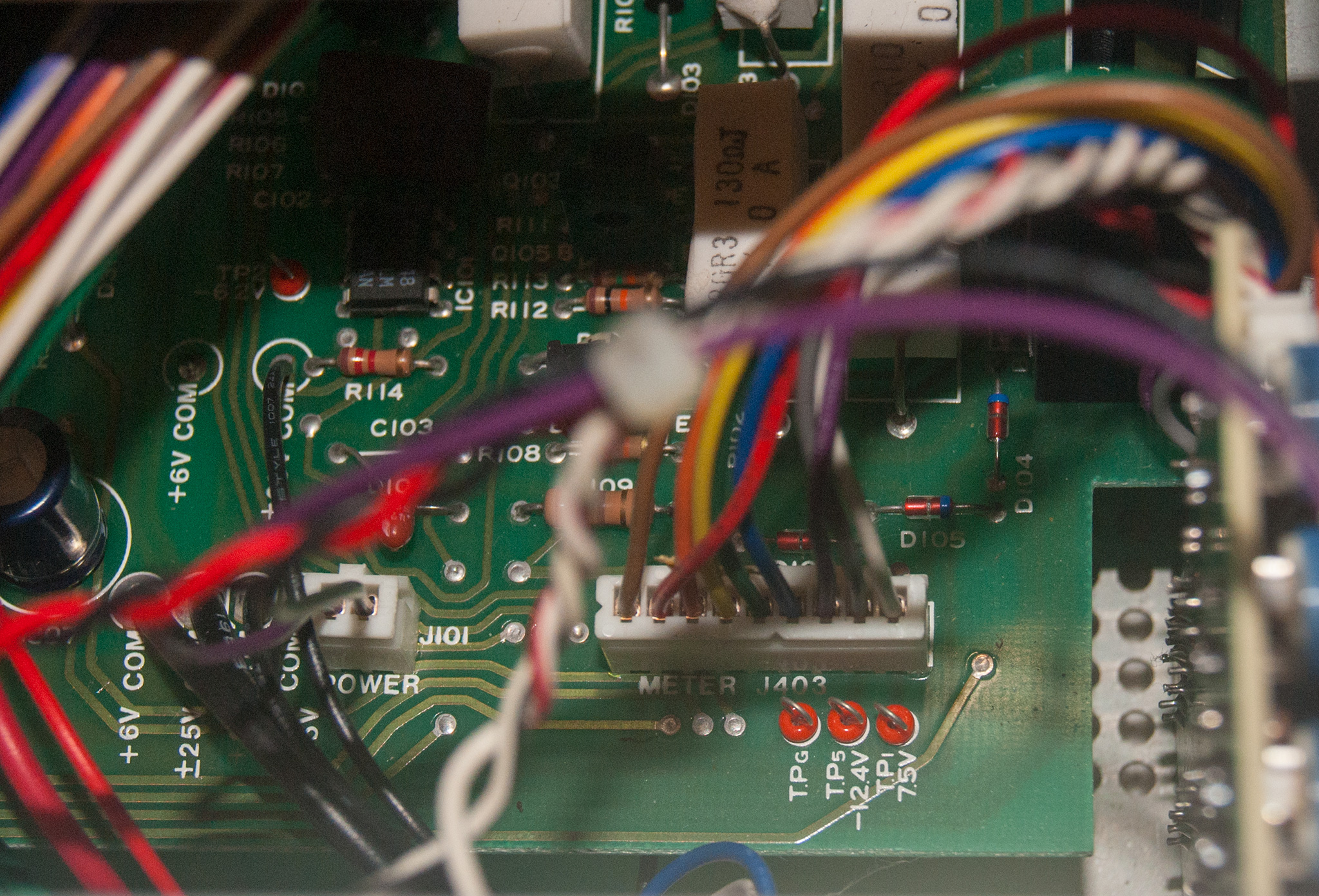
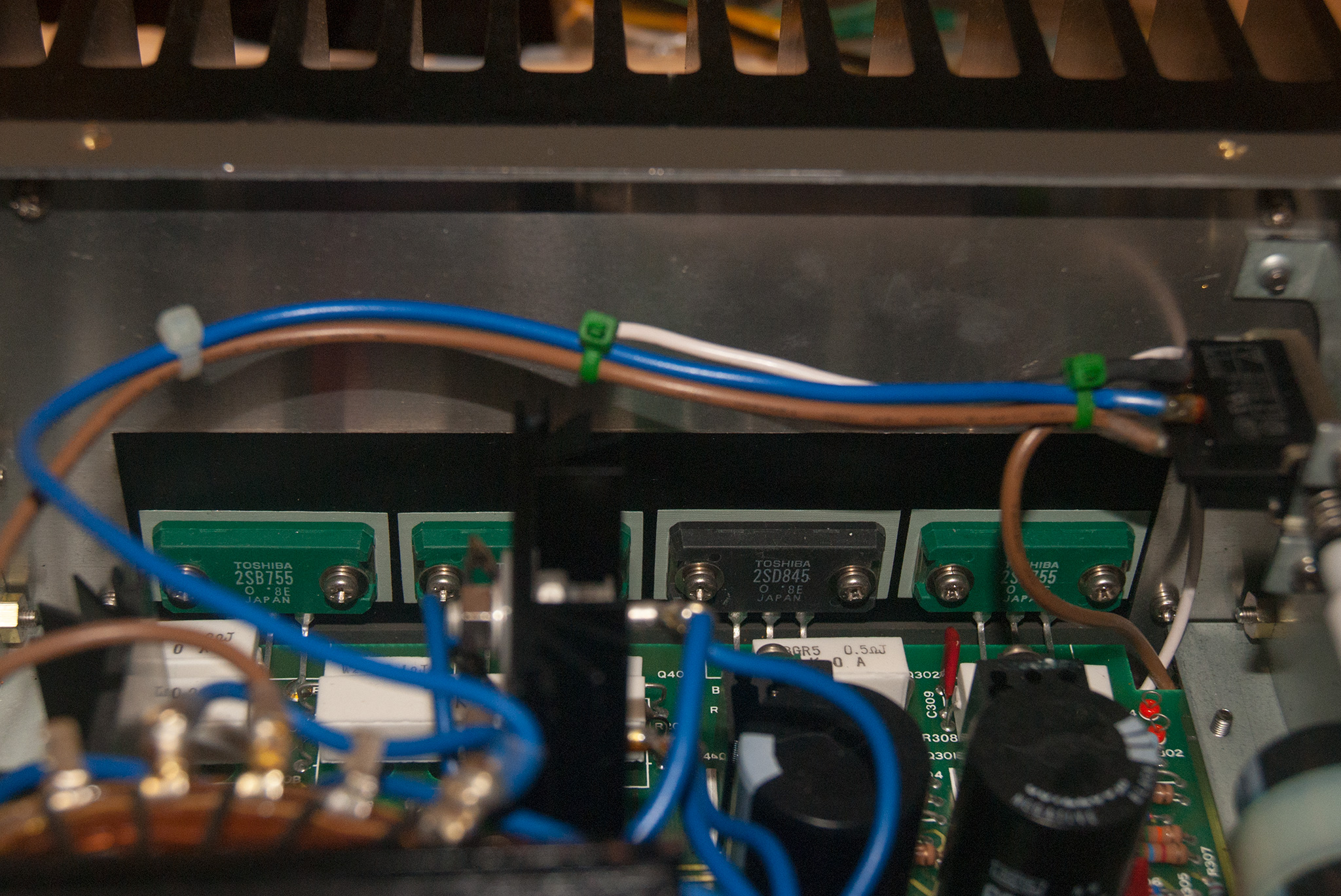
Test points are liberally sprinkled across the board, with voltages clearly marked on the silkscreen. I'll certainly be able to repair things if that ever proves necessary. And I had to take note of the four huge transistors across the back. They're obviously doing the bulk of the regulation work. I looked into the schematics of various supplies for a bit as I was shopping around, trying to understand why they are so expensive. It didn't help; several schematics fit easily on a single page, and (at least for the basic models) are virtually all just a beefy linear regulator tied to an opamp or to to control regulation. The same goes here except that the circuit is all discrete parts. Not a linear regulator IC, but discrete components set up to do the same job.

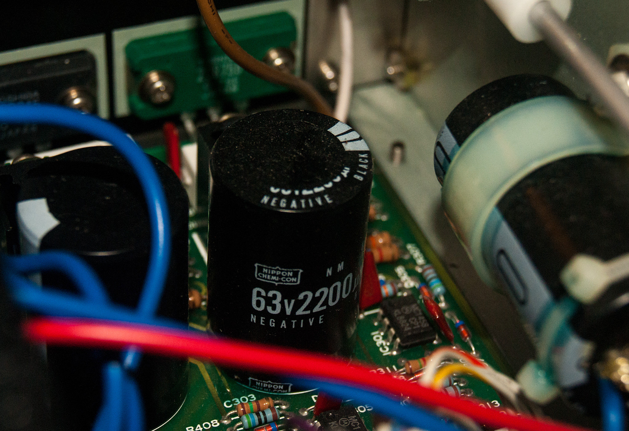

Finally let's wind down with some fun smaller points. As I said above there are only four ICs. Two of them (one smack dab in the center, one nearly hidden by shadow in the top right) show a likely date code: 24th week of 1988, which if correct means this is a twenty seven year old unit, and still working great. The capacitors are mostly very hard to see, but as best I can tell, like this one that is clearly visible, they're all Nippon Chemicon, which is a top quality brand. Probably helps explain why this thing still works great after almost three decades. Also a fun product design note: the power button is (appropriately) on the front panel, but the actual switch is all the way in the back. A metal rod carries the force all the way along the body. Look carefully and you can see a tiny set screw holding things together. Another indicator of quality design; a price-optimized unit would probably have done something cheaper like a friction fit, more likely to wear out, possibly beyond repair, over time.
So, overall I'm quite pleased with my purchase. It was a steal at only $30 (plus $22 shipping). Hopefully I won't blow up any more things now that I have it!
2016-03-27 20:27 - JoJo99
Thanks for the manual for my LPS-152! I have my manual around here somewhere... (c;
I got my '152 for free--a guy upgraded to something with "Agilent" or such on the label. It worked fine until recently. The 0-25v is not working. Gotta tear into it, which I can now do thanks to you!
Enjoy, JJ