Nevo C2 Remote Control - Reverse Engineering - Part 2
2016-03-09 22:14 - Making
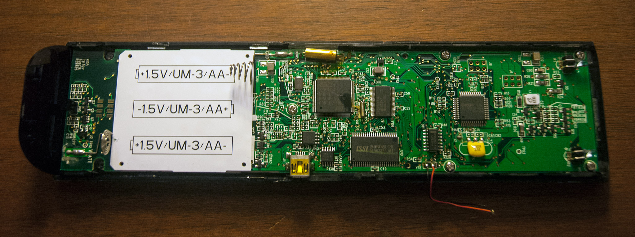
For context see part 1, which has pictures and descriptions of the chips I'm referencing.
The important bits are two microcontrollers: one ARM made by ST, ("Chip 1") one 8-bit made by Samsung ("Chip 7"). I'll be referring to them as ARM and SAM8, respectively. Plus three connectors. There's J6 and J8, both close to the SAM8, both two by three standard 0.1" pitch headers, unpopulated. Then a completely unlabeled two by four arrangement of rectangular pads next to the batteries, far from any chips. I'm calling this one JX, for either eXtra or eXternal -- this one is accessible without disassembling the remote at all, just by opening the battery compartment. I've figured out what these all do, so let's share!
J6
Just like J8 to come pin one is clearly marked as the singular square pad of the six, plus the notch on the silkscreen layout. Orient yourself so it's top left and I've chosen to label the pins counter-clockwise like a standard IC package. All of these are connected through to the ARM controller, like so:
| J6 Pin | ARM Pin |
|---|---|
| 1 | P1.3 UART2_RX |
| 2 | P1.5 UART2_TX |
| 3 | GND |
| 4 | VDD |
| 5 | P1.0 UART1_TX |
| 6 | P1.1 UART1_RX |
I was quite confused for a while at the selection (port 1, pins 0 1 3 5, skipping 2 and 4??) for a while until I found, on pin 47 of its data sheet the alternate functions available on those pins, and the pattern seemed clear. I'm mildly surprised to see two UARTs broken out, perhaps the software dedicates one to sending and one to receiving, or command/debugging output, or some other combo? Or perhaps one is unused, "just in case" design. Certainly it will be interesting to check, but I doubt it will be much use on its own.
J8
Also located just next to the SAM8, this is clearly a programming header for it:
| J8 Pin | SAM8 Pin |
|---|---|
| 1 | VDD |
| 2 | GND |
| 3 | TEST |
| 4 | SCLK |
| 5 | SDAT |
| 6 | nRESET |
Unfortunately data on this line of micros looks sparse. I can see these pin names, and a bare description of their function, in the data sheet, and it makes sense as a synchronous serial channel, and the TEST/nRESET pins to force it into programming mode. But what protocol goes over this channel? I surely don't know. The data sheet also has a surprising list of development tools listed, but none of them are common things. I could only find concrete evidence of one, a storefront with no price listed, which makes me think "If you have to ask how much it costs, you can't afford it." Certainly not for a hobby project! Slightly better news, I found concrete evidence of this particular micro model in use for other UEI remotes (specifically JP1.3). This is clearly the driver for the infra-red side of the remote, which works fine, so I don't need to mess with it. And maybe I can find some community reference, even if just source code, for how JP1.3 works, and maybe it's just the flashing protocol for this micro?
JX
The main attraction was saved for last. Given the lack of markings I have to make up my own numbering scheme. So, with the remote oriented as pictured, see that it is two columns of four pads. Pin one is the top left, and they go counter clockwise from there. With that set, I can show the map to ARM pins:
| JX Pin | ARM Pin |
|---|---|
| 1 | JTDI |
| 2 | JTMS |
| 3 | JTCK |
| 4 | JTDO |
| 5 | VDDQ |
| 6 | JTRSTn |
| 7 | RESET_INn |
| 8 | GND |
Jackpot! This is clearly the JTAG debugging header for the ARM micro! This is without a doubt the next area for me to concentrate on. I know what JTAG is, but so far very little about how it works. I've got an ST-LINK device, used for STM32 (ARM Cortext) work in the past which might be enough to move forward with. And if so that should give me full access to the ARM and whatever it has stored inside, plus I think I should be able to bit-bang SPI to the external flash chip as well, at least. I've mapped its pins to the SSP0 port on the ARM, no surprise, so it's accessible that way.
Fun aside: this had me very confused at first. For the lamest of reasons: I carefully counted out the pins and double-checked them all, thanks to the narrow pitch. I knew which went where for sure, looked them up and they made no sense. Only after a few back-and-forth attempts did I finally take notice of the "pin 1" marker on the chip. It's rotated 90 degrees counter-clockwise from the "natural" orientation. Compensate for that and the JTAG pins all jumped out.
2016-04-27 10:39 - jjrh
Recently bought this remote too, hope to also do some hacking - looking forward to part 3!