VFD Clock Prototype
2015-07-20 18:34 - Making
Some time around early May I discovered the IV-22 (NB-22, ИB-22) Vacuum Fluorescent Display tube. This is an old Russian technology from (I think) the 1960s. It's a standard seven-segment digit display like in modern electronics, but it's a vacuum tube, and it's a fluorescent display. I'd been interested in a big enough project to experiment with the STM32 processor as well, so I decided to make a clock out of them. I've only been trying off-and-on, including some waiting for the mail, but it has taken me since May, it's not a small project.
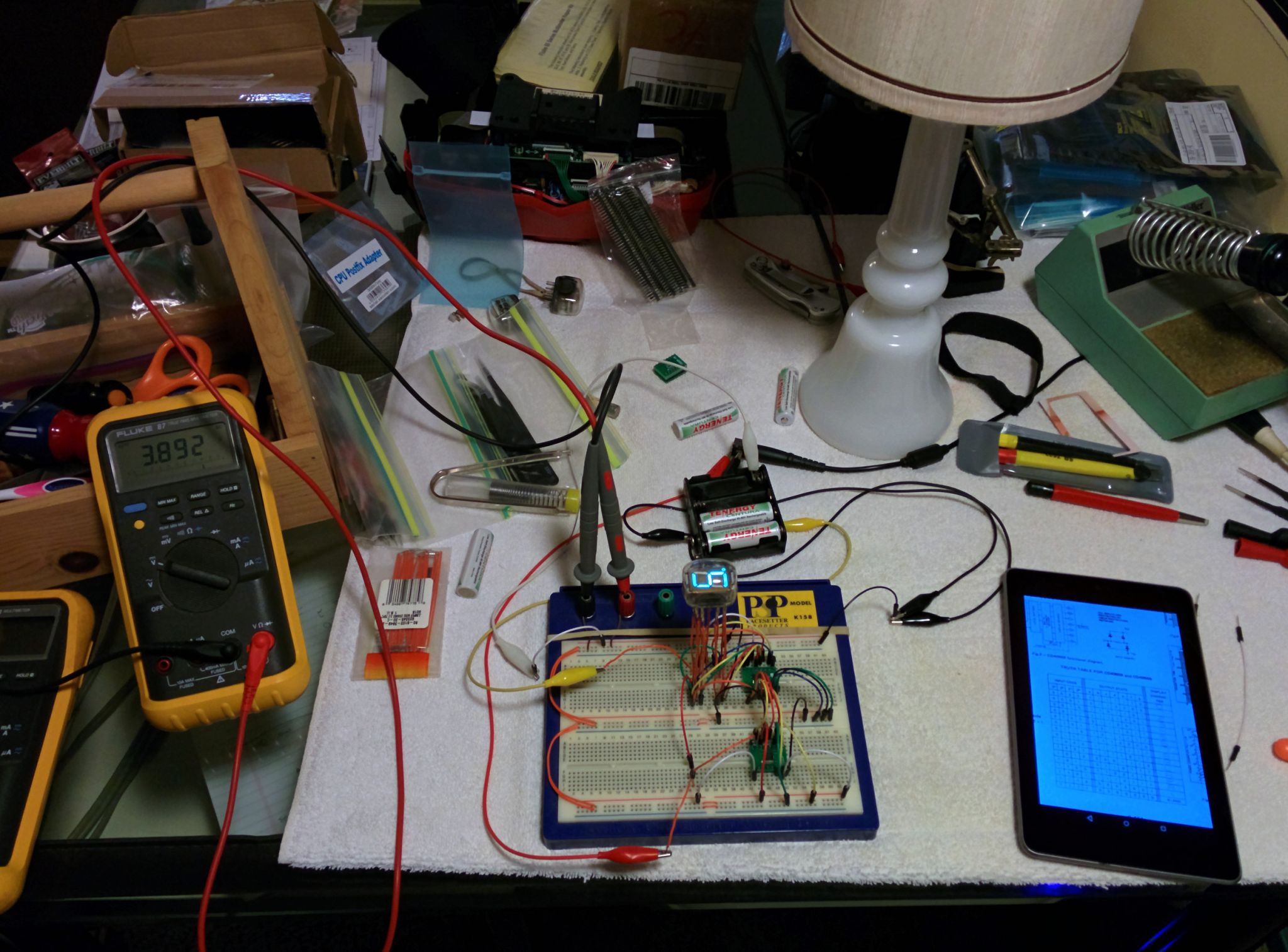
And here's where I've gotten: the first working, though very simple, prototype. VFD tubes are a cousin of the (slightly) more famous Nixie tubes. Nixies can require up to 150 or 200 volts to illuminate. VFDs are not so demanding, they can light up with as little as 12 volts, but really "want" 20 to 30. The only truly complicated bit is that you also need a very low voltage (just over one volt) to power another part of it. Both very low and middling high means you have to design carefully.
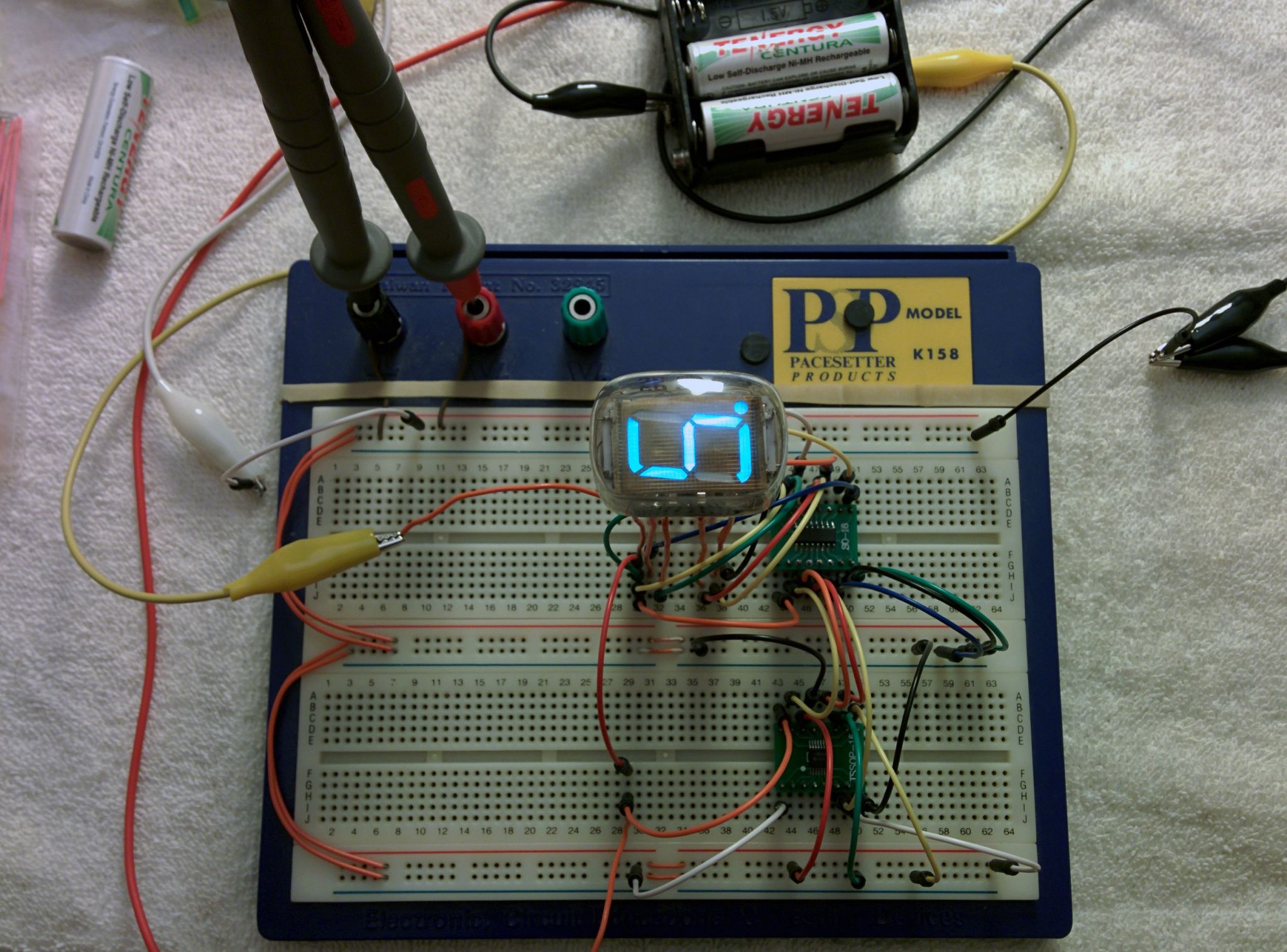
Here I'm running it from just shy of 20, with two chips. The chip on the bottom (a CD4504) translates low voltage input signals (3.3 V) to that high level (20 V). The top chip is a decoder/driver (a CD4056); each digit needs one, but it shares the input signals and keeps the right segments displayed the whole time. You can see I've got it displaying a 5, with the decimal point on too. The bluish glow of the fluorescent phosphor is pretty unique. And the VFD technology is also very interesting.
Just by plugging the four wires in the very bottom right into a low-(logic-)level high or low I could easily get the driver chip to display all the digits. Ironic enough though this is the first tangible result, I'm actually almost done! All along I've been designing (and re-designing) the circuit, and the PCB to hold all the parts. Once I was convinced I had a working design, I ordered the parts, waited for the mail, and tried a test. That's when I realized that while the CD4056 has level shifting built in, it's not compatible with the specific kind I need to do. So I placed another order including the CD4504 chips, waited for the mail again, and then performed this successful test.
Now all I've got to do is relax, double check everything, make sure ... Then order the PCB, the most expensive part. And wait for it in the mail. And put it together. And finish writing the software that will actually make it a clock, rather than a complicated paper weight. Maybe I'm not almost done.